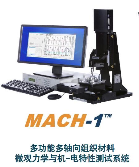
生物软组织应力松弛和蠕变试验装置-BMM 高分辨率、多功能、组织材料微观生物力学测试分析系统
型号:MachOne
联系人:李先生
联系电话:18618101725
品牌:BMM
高分辨率、多功能、组织材料微观生物力学测试分析系统
之生物软组织应力松弛和蠕变测试分析
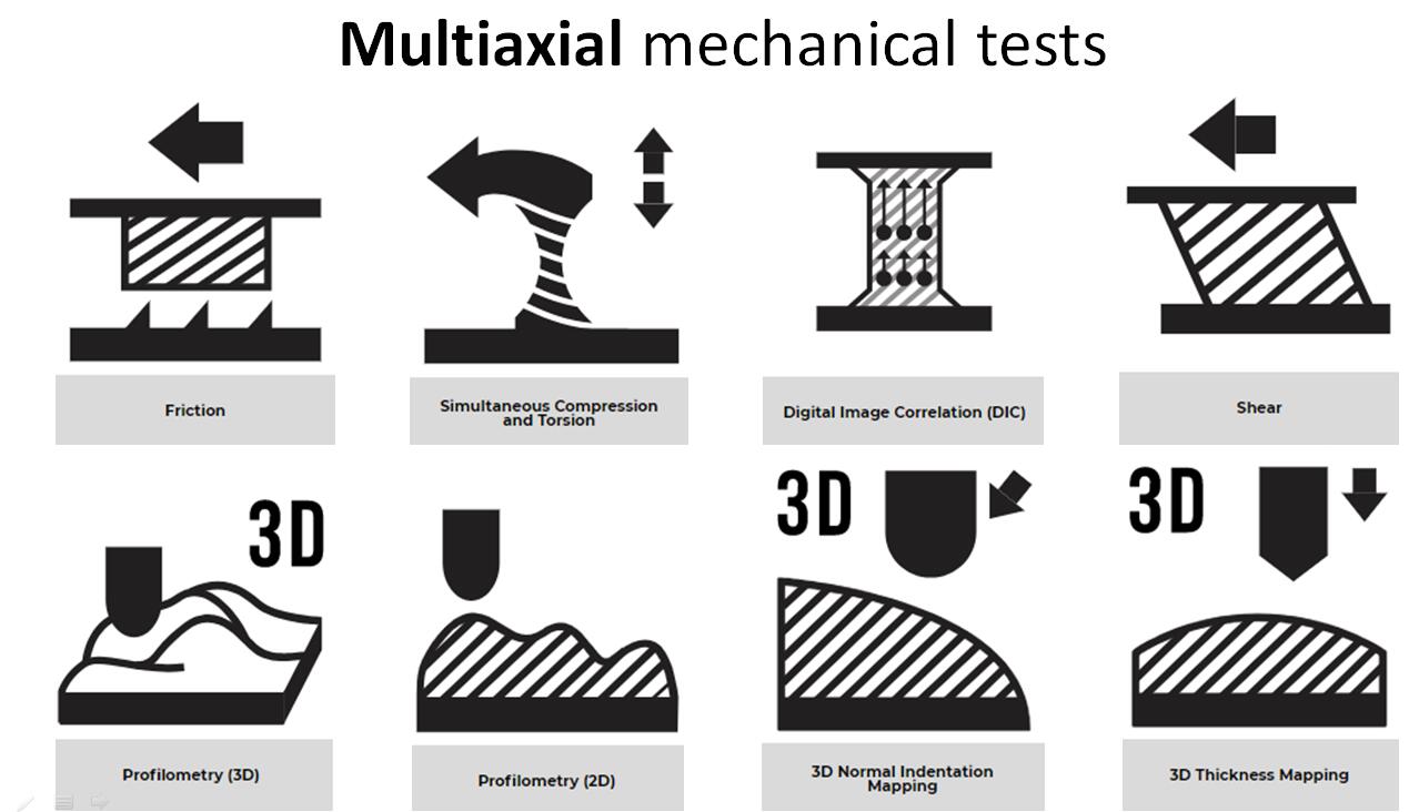
-多载荷多物理场耦合微观力学性能原位测试系统
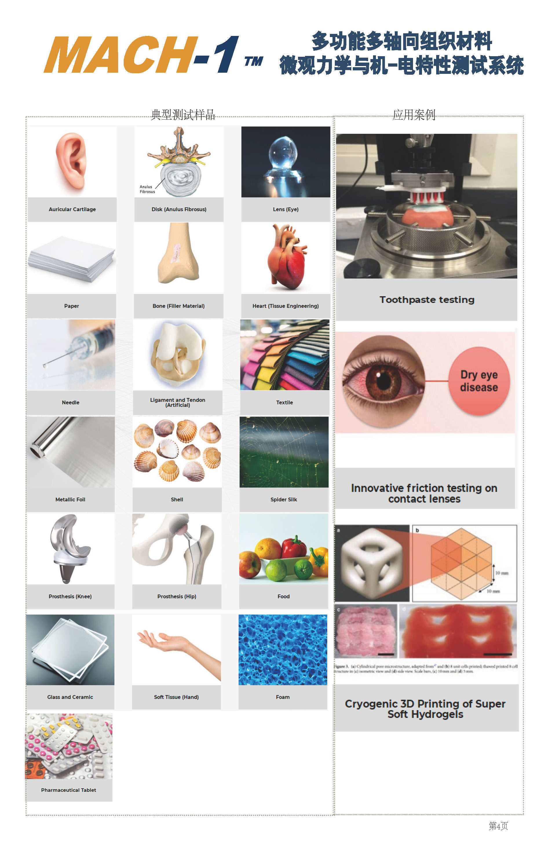
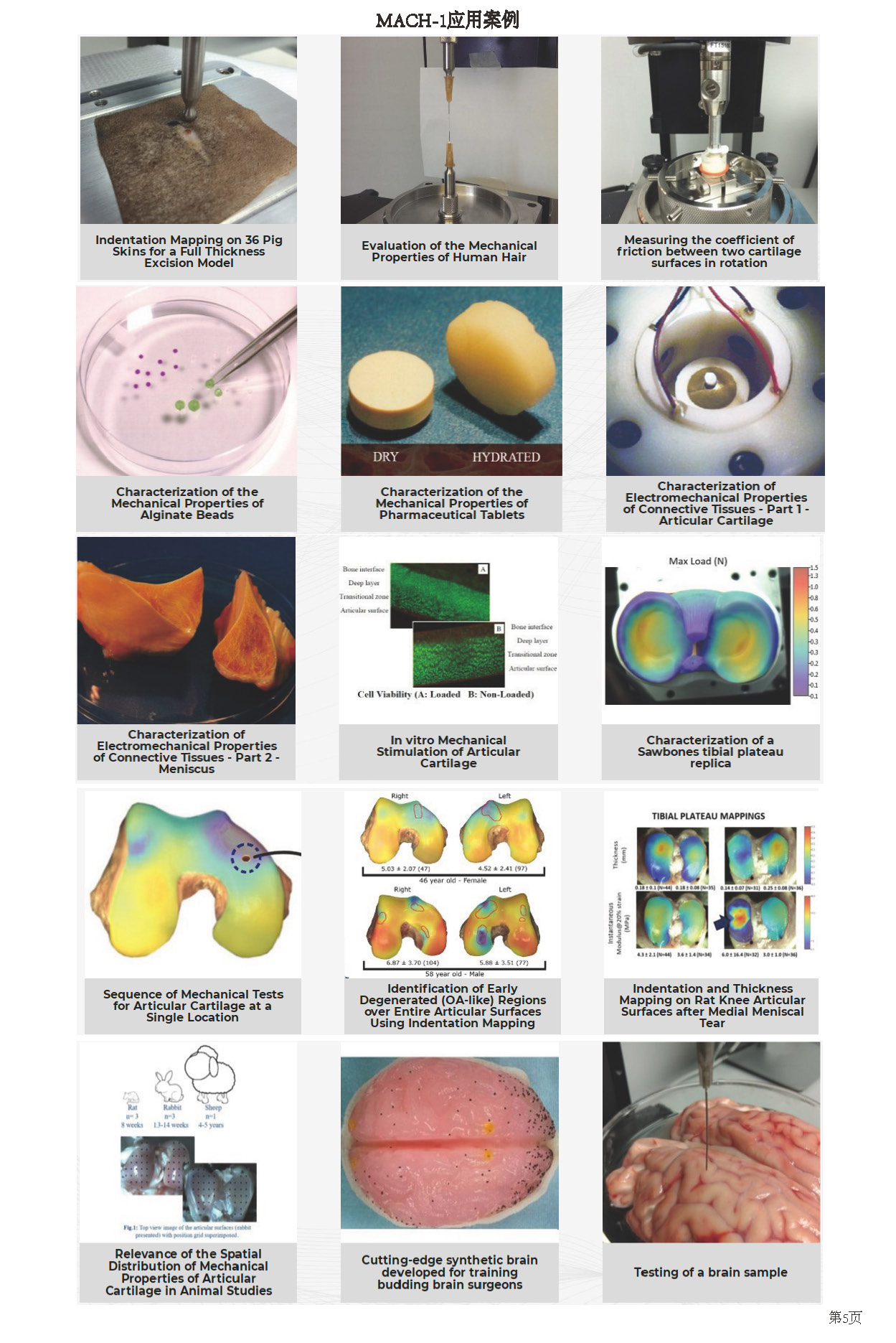
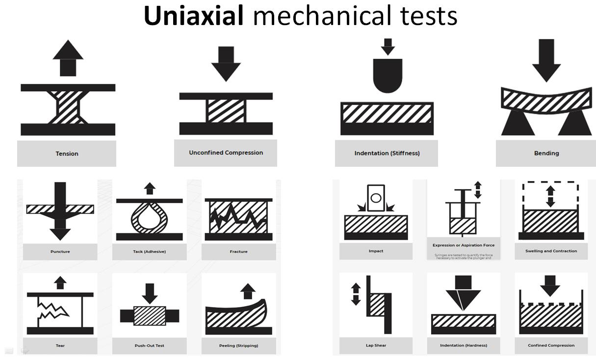
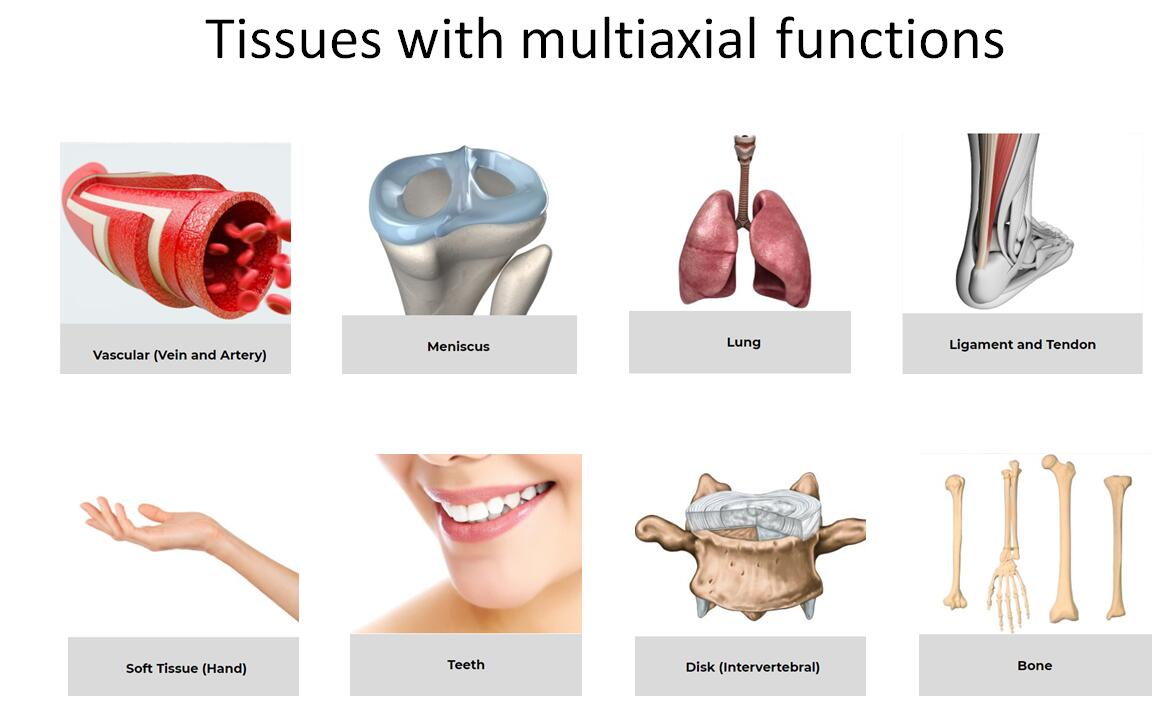
该多轴多功能微观力学动态静态蠕变波形加载测试分系统集成压缩,拉伸,剪切,扭转 ,压痕摩擦,弯曲,穿刺,撕裂等各种高分辨率测试分析功能,适用软硬单丝生物组织材料测试。
|
纤维丝张力和扭力测 |
应力松弛函数 |
大鼠主动脉段多步应力松弛试验与分析 |
型号:MachOne
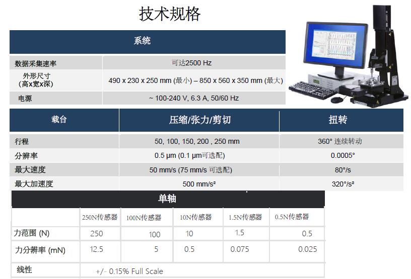
该系统是能集成压缩、张力、剪切、摩擦、扭转和2D/3D压痕、3D轮廓及多力混合耦连测试的一体化微观力学测试装置。能对生物组织、聚合物、凝胶、生物材料、胶囊、粘合剂和食品进行精密可靠的机械刺激和表征。允许表征的机械性能包括刚度、强度、模量、粘弹性、塑性、硬度、附着力、肿胀和松弛位移控制运动。 特点
1、适用样品范围广:
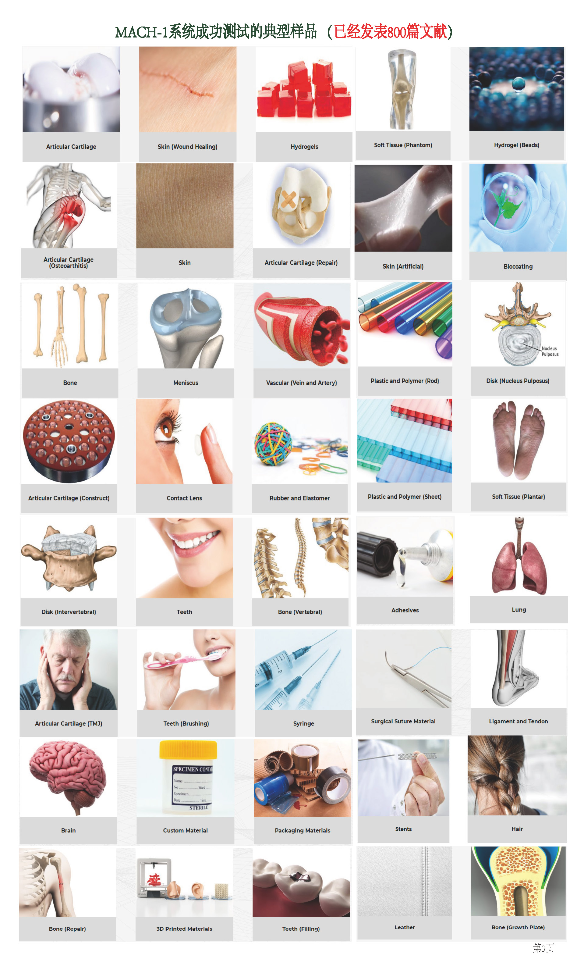
1.1、从骨等硬组织材料到脑组织、眼角膜等软组织材料
1.2、从粗椎间盘的样品到j细纤维丝
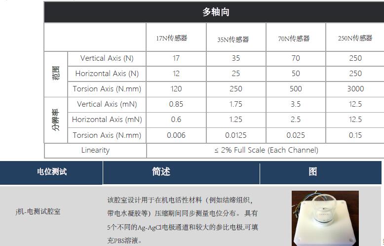
2、通高量压痕测试分析 2.1、三维法向压痕映射非平面样品整个表面的力学特性 2.2、48孔板中压痕测试分析 3、力学类型测试分析功能齐 模块化集成压缩、张力、剪切、摩擦、扭转、穿刺、摩擦和2D/3D压痕、3D表面轮廓、3D厚度等各种力学类型支持,微观结构表征及动态力学分析研究 4、高分辨率: 4.1、位移分辨率达0.1um 4.2、力分辨率 达0.025mN 5、 行程范围广:50-250mm 6、体积小巧、可放入培养箱内 7 、高变分辨率成像跟踪分析 8、多轴向、多力偶联刺激 9、活性组织电位分布测试分析 10、产品成熟,文献量达 上千篇
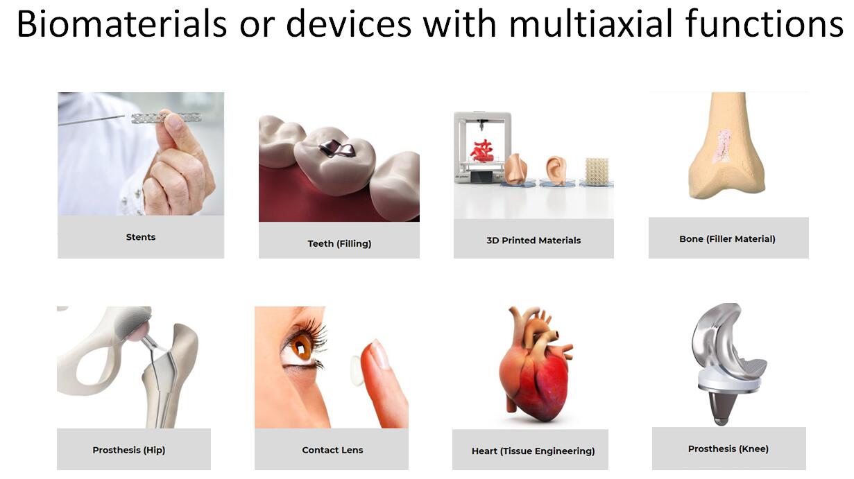
该微观力学测试分析与培养系统初该系统为软骨力学性能检测所研发,此后集成了多种配置以满足更多生物组织和软质材料力学性能的测量和评估。该仪器卓越性能特点--模块化设计,简易操作平台,面向用户设计,广泛应用于生物材料检测,高分子材料检测以及数字教学等领域,产品得到了业界广泛的认可和推广。该系统
相比于传统的大型力学测试系统,该微观力学测试系统总体较小,可以实现桌面化的操作流程,操作过程简便。该系统测试方法面,是多样化的材料力学表征工具,是科学家、工程师和其他各领域用户的佳选择。在动态力学分析、薄膜、复合物、聚合物、生物产品、医学鉴定和水凝胶等领域都有广泛应用。
How does the creep function works?
联系人:李先生
联系电话:18618101725
品牌:BMM
更多介绍
多功能组织材料生物力学特性、电位分布测试分析表征系统

纤维丝张力和扭力测
自动法向压痕和厚度映射
胫骨三维轮廓测试
机电活性材料(如结缔组织、带电水凝胶等)压缩过程中电位分布
典型测试材料: